
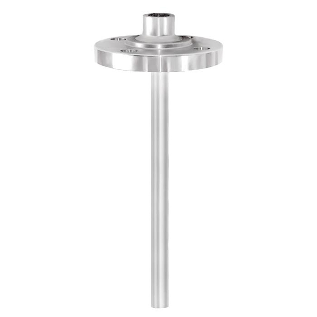
Images are representations only.
Thermowell with Threaded Flange (Solid-Machined) - TW10-B, TW10-S
Description
Each thermowell is an important component of any temperature measurement point.
It is used to separate the process from the surrounding area, thus protecting the environment and operating personnel and keeps aggressive media, high pressures and flow rates from the temperature sensor itself and thereby enables the thermometer to be exchanged during operation.
Features- Connection between flange and thermowell in threadwelded design
- Model TW10-S: No directly wetted welded joints (standard). Model TW10-B: Additional weld seam on the process side (sealing joint)
- Coating for corrosive or abrasive process loads
- Possible thermowell forms:
- tapered, straight or stepped
- “Quill Tip” version (with open tip)
Specifications
Specifications
Thermowell Material
- Stainless Steel 304/304L, 316/316L, 1.4571 A105, Special materials
Flange
- Threaded Flange to ASME B16.5
Connection to Thermometer
- 1/2” NPT, G 1/2 Female “Quill Tip” version with weld-in Connection 1/2” and 3/4”
Bore Size
- Ø 8.5 mm
- Ø 6.6 mm
Insertion Length U
- To Customer Specification
Connection Length H
- 57, 83, 102 mm (Standard) Others on Request
Coating
- ECTFE (Halar) Thickness min. 0.6 mm
- PFA Thickness min. 0.4 mm (Standard) or min. 0.6 mm (Special Design)
- Corrosion Protection for high chemical loads:
- Air Plasma Spraying (APS) Thickness Max. 1.6 mm
- Laser cladding Thickness 1.6 mm (Standard) Higher thickness on Request
- Plasma Transfer Arc (PTA) Thickness 1.6 mm (Standard) up to 3.2 mm
- High Velocity Oxide Fuel (HVOF) Thickness 0.5 mm
- Hardfacing for abrasive process loads with Stellite® 6:
Maximum Process Temperature, Process Pressure
- Process Conditions
- - Flange pressure rating
- - Coating
- - Material
- - Dimensions
- Thermowell Design
- Depending on:
- - Flow rate
- - Density of medium
Applications
Typical Applications
- Petrochemical industry, on-/offshore, plant construction
- For high process loads