Images are representations only.
Kayden CLASSIC 812 Thermal Flow, Level & Interface Switch
Description
- Process Connection
- Raised Face or RTJ Flange
- Adjustable Set Point Range
- 0 - 254 feet/s
- 0 - 77 metres/s
- Insertion 'U' Length
- inch 2.5" to 120" in 1/2" increments
- cm 6.4 to 305 in 1 cm increments
- Input Power
- 12-24 Vdc & 115-230 Vac, 50-60 Hz
- Operating Pressure - Maximum
- Per Flange Rating, ASME B16.5
- Temperature Range - Sensor
- -55° to 200° C
- -67° to 392° F
- Local Enclosure
- Aluminum Flameproof
- 1" Female NPT Conduit Connection
- Local Enclosure Cover
- Blind or Glass Lens, Flameproof
- Wetted Materials
- 316/316L Stainless Steel
- Other Materials Available
- Outputs/Communications
- Two Independent Relays - SPDT
- 4-20 mA
- Modbus
- Rated 120 Vac max, 30 Vdc max, 4 A max
- Approvals
- CSA
- CRN
- Single Seal
- NACE
- NEMA 4, 4X, 6P, IP65/67
Inventory
Displaying prices & availability for Ohio, United States 43201 in USD. Change location or currency.
- Process Connection
- 316 Stainless Steel Flanged
- Raised Face 2"
- ANSI: 300
- Adjustable Set Point Range: 0-254 feet/s, 0-77 meters/s
- Insertion 'U' Length: 5"
- Input Power: 12-24 VDC & 115-230 VAC, 50-60 Hz
- Operating Pressure (Maximum): Per Flange Rating, ASME B16.5
- Temperature Range (Sensor): -45°C to 200°C, -50°F to 392°F
- Local Enclosure: Aluminum Flameproof, 1" FNPT
- Cover: Flameproof Glass Lens Cover
- Remote Electronics Enclosure and Cover: Not Required
- Wetted Materials
- 316 Stainless Steel
- Outputs/Communications
- Two Independent Relays (SPDT)
- 4-20 mA (Thermal Signal, Scalable)
- Modbus Communication via RS-485
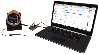
- RCMS (Remote Control & Monitoring Software)
- Electronics - Standard Features
- Automated Redundant Self-Test Diagnostics
- Display Panel Lock-Out
- Easy Set-up
- No Mechanical Jumpers or Trim Pots
- Intelligent Push Button Interface
- Constant Display of Operation (Flow/Level)
- Start-Up Bypass Timer
- Approvals: c CSA us (UL Standards), CRN (Canada-wide), Single Seal, NACE, NEMA 4 [/li]
Configure
Specifications
Specifications
Brand
Applications
- Flow
- Level
- Interface
Principle of Operation
- Thermal, Calorimetric
Sensor, Probe Style
- Insertion Flanged
Insertion 'U' Length - Custom
- 6.4 cm to 305 cm (in 1 cm increments)
- 2.5" to 120" (in 1/2" increments)
Flange Type
- RF - Raised Face
- RTJ - Ring Typical Joint
Flange Class
- 150#
- 300#
- 600#
- 900#
Flange Size
- 1" DN 25
- 1-1/2" DN 40
- 2" DN 50
- 3" DN 80
- 4" DN 100
- 5" DN 125
- 6" DN 150
- 8" DN 200
- 10" DN 250
Flange Material
- 316, 316L Stainless Steel
- Hastelloy C-276
- Titanium Grade 2
- Other metals available
Wetted Materials
- 316, 316L Stainless Steel
- Hastelloy C-276
- Titanium Grade 2
Sensor Construction
- All-Welded Construction
Operating Pressure Maximum - Sensor
- Per Flange Rating, ASME B16.5
Operating Temperature - Sensor
- -55° to 200° C
- -67° to 392° F
Operating Temperature - Electronics
- -55° to 65° C
- -67° to 149° F
Switch Point Range
- Air & Gases: 0.25 to 200 sfps, 0.08 to 60 smps - Standard Condition 21° C (70° F) at 14.7 psi (1 Atm)
- Hydrocarbon-based Liquids: 0.01 - 5.0 fps, 0.003 - 1.50 mps
- Water-based Liquids: 0.01 - 3.00 fps, 0.003 - 0.9 mps
Response Time
- Approximately 0.5 to 30 seconds
Accuracy
- Flow Service: ± 1.0 % of Set Point Velocity over Operating Range of ± 28° C (± 50° F)
- Level Service: ± 0.64 cm (0.25")
Switch Type
- 2 SPDT Sealed Relay Contacts Rated @ 4 Amps Resistive 230 Vac or 30 Vdc, Max.
Input Power
- 12-24 Vdc, 120-240 Vac, 50/60 Hz
- Power Consumption: 6 Watts Max. Fully Configured
- Universal Power Input
Output
- 4-20 mA (Thermal Signal, Scaleable) Rates 120 Vac, Max.
Communication
- Modbus RTU Communication-Alarms, Flow Status & Diagnostics
- RS-485 Using Kayden's Remote Control & Monitoring Software (RCMS) or other Modbus Compatible Software
Approvals & Certifications
- Canadian Standards Association Details:
- CSA Mark with "C" and "US" or with NRTL
- CSA - Input/Supply Rated 12/24 VDC or 120/240 VDC, 50/60 Hz, 6 W Max.
- CSA - Output/Contacts Rated 120 VAC Max., 30 VDC Max., 4 Amp Max.
- CSA - Ambient Temperature Rating: -55° C to +65° C (-67° F to +149° F)
- CSA - Process Temperature Range: -55° C to +200° C (-67° F to +392° F)
- CSA - Temperature Code: T3
- CSA - Enclosure Type: 4, IP55
- CSA - Local (Sensor) Enclosure Flameproof: Class I, Div. 1, Groups B, C, D, Ex d IIB + H₂ AEx d IIB + H₂ (Class I, Zone 1, Group IIB + H₂) Temperature Code: T3 Enclosure Typical 4, IP55 Single Seal Approved per ANSI / ISA 12.27.01-2003
- CSA - Remote Electronics Enclosure - Optional Flameproof: Class I, Groups B, C, D, Ex d IIB + H₂ AEx d IIB + H₂ (Class I, Zone 1, Groups IIB + H₂) Temperature Code: T3
- Canadian Registration Number Details:
- CRN - All Provinces & Territories of Canada
- CRN - Material: 316/316L Stainless Steel
- CRN - Process Connections: Class 150, 300, 600, 900. 1 to 10 NPS.
- CRN - Insertion Lengths: 2.5" to 120" (6.35 to 304 cm)
- CRN - Maximum Working Pressures:
- CRN - Class 150: MWP* : 275 psi, 1896 kPa, 18.96 bar
- CRN - Class 300: MWP* : 720 psi, 4964 kPa, 49.64 bar
- CRN - Class 600: MWP* : 1440 psi, 9928 kPa, 99.28 bar
- CRN - Class 900: MWP* : 1990 psi, 13,720 kPa, 137.20 bar
- Maximum Working Pressure derated by temperature and per the rating of the flange class. ASME B16.5-2020, Table 2-2.2C.
- CRN - Temperature Range: -55° C to +200° C (-67° F to +392° F)
- CRN - Code of Construction: ASME B31.3
- CRN - Canadian Registration Numbers - Flanges Approved for All Provinces & Territories 812-RAA Series: CRN 0F22124.2C, 316, 316L Stainless Steel, Pipe NPS 1/2" Schedule 80 Code of Construction: ASME B31.3, Max.
Electronics - Standard Features
- *Configurable only from the Kayden RCM Software
- 100 % Digital Design. Electronics are Environmentally Sealed
- 4-Adjustable Independent Switch Point Timers
- Automated Redundant Self-Test Diagnostics
- Display Panel Lock-Out*
- Easy Setup: No Mechanical Jumpers or Trim Pots
- Incrementally Adjustable Heater Power (5 % Steps) with Automatic Over-Range Protection
- Intelligent User Interface with Push-Button & Constant Display of Operation (Flow/Level)
- Start-Up Bypass Timer
- Temperature Compensation
- Temperature Mode*: Process Temperature may be Displayed/Graphed in Flow/Level Mode
Remote Control & Monitoring Software
- Adjust Relay Modes
- Adjust Set Points 1 & 2
- Load or Save User Settings
- Lock or Unlock the Display Panel to Protect the Settings
- Many Other Adjustable Features
- Modify Heater Settings to Optimize Response Time
- Monitor Operating Status
- Operated Via a Personal Computer Locally or from a Remote Control Center
- Visualize the Actions of the Process Via the Graphical Display
Environmental Protection
- IP55
- NEMA 4 / IP55
Local Enclosure Conduit Connection
- 1" NPT Female Conduit Connection
Local Enclosure & Cover Material
- Copper-Free Aluminum (Does Not Exceed 0.4 % Copper)
Local Enclosure Cover
- Buna-N O-Ring on Cover
- Blind Cover - Flameproof
- Glass Lens Cover - Flameproof
Local Enclosure & Cover Finish
- Powder-Coated Polyester TGIC
Remote Electronics Enclosure Cover
- Glass Lens Cover - Flameproof
Remote Electronics Enclosure & Cover Finish
- Powder-Coated Polyester TGIC
Storage Temperature
- Store in a clean & dry environment between -30° & 60° C (-22° & 140° F)
Applications
Applications
- Ammonia Storage
- Biogas Flow
- Catalysis Vessels
- Chemical Injection & Additive Flow Monitoring
- Chemical Reactors
- Chlor-alkali Processes
- Compressors
- Condensers
- Deionization Tanks
- Digester Gas Flow
- Distillation Columns
- Drain Line Flow
- Emergency Eye Wash & Shower Stations
- Fermentation Vessels
- Flare Gas Monitoring
- Flare Knock-out Drums
- Flow Monitoring & Verification
- Heat Exchangers
- Heat Recovery Steam Generator (HRSG) - Power & Utilities
- High Pressure Flows
- Leak Detection
- Lube Oil Systems
- Monitoring Purge Air Flow
- Natural Gas to Boilers
- Pumps
- Reboilers
- Refinery Flow Applications
- Relief Valve & Rupture Disk Flow Monitoring
- Remote Indication of Flow via Analog Output & Digital Communications
- Pump Protection - Dry Alarm
- Tank Blanketing
- Tank Overflow Protection
- Tanker Loading & Unloading
- Water & Wastewater
- Vaporizers
- Vent Monitoring
- Biogas Dehydration
- Blending Operations
- Carbon Slurry Level
- Compressor Scrubber
- Compressor Waste Liquid
- Condensate Receiver Tanks
- Cooling Tower Basins
- Crude Desalting
- Crude Dehydration
- Deionization Tanks
- Digester Blow Tanks
- Free Water Knock-out Tanks - High, Low and Interface Level
- Geothermal - Degasser Tanks
- Geothermal - Steam & Brine Separators
- Leak Detection (Accumulation Reservoir)
- Lime Slurry Level
- Mixing & Blending Systems
- Oil Separators & Treaters - High, Low & Interface Level
- Production Fluid Storage
- Pulp Bleaching Towers
- Pulp Digesters
- Pulp Storage
- Pulp Washing Systems
- Sampler Systems
- Sand Separators
- Scrubber Vessels
- Storage Tanks
- Sumps - All Types of fluids: Water, Oil, etc.
- Surge Tanks
- Tank Overflow
- Turpentine Recovery
- Vapor & Liquid Separation
- Vapor Recovery
- Crude Desalting
- Interface Control in Separation Vessels
- Interface Detection
- Interface Control & Level Detection in Settling Vessels
- Liquid-Liquid Extraction - LLX
- Liquids, Air & Gases
- Slurries
- Corrosive Liquids
- Flameproof, Hazardous & General-Purpose Areas
- Consistent Process Composition & Temperature
- Sufficient Straight Run Flow Profile (minimizes turbulence)
- Recommended Minimum of 5 Pipe Diameters from any Disturbance
- Consistent Process Composition & Temperature
- Sufficient Straight Run Flow Profile (minimizes turbulence)
- Clean and Dry
- Consistent Process Composition & Temperature
- Sufficient Straight Run Flow Profile (minimizes turbulence)
- Consistent Process Composition & Temperature
- Sufficient Straight Run Flow Profile (minimizes turbulence)
- Inconsistent Process Composition or Temperature
- Insufficient Straight Run
- Aerated Fluids
- Turbulence
- Inconsistent Process Composition or Temperature
- Wet or Saturated Air & Gas
- Inconsistent Process Composition or Temperature
- Insufficient Straight Run
- Aerated Fluids
- Turbulence
- Inconsistent Process Composition & Temperature
- Insufficient Straight Run
- Aerated Fluids
- Turbulence
- Dry granulated processes are NOT good candidates for thermal switches
Pump Protection
Pump Protection
Thermal Dispersion Flow Switches for Pump Protection
In a wide range of industrial environments—from petrochemical processing and wastewater treatment to power generation and food & beverage production—pumps serve as vital components for fluid transfer and circulation. Ensuring their dependable and efficient performance is essential for maintaining throughput, product quality, and operational safety. However, conditions such as dry running, obstructed suction or discharge lines, and cavitation can cause substantial equipment damage, inflated maintenance costs, and compromised process integrity.
Thermal dispersion flow switches have proven to be effective tools for identifying these problematic scenarios early. By providing timely interlocks, they help prevent costly breakdowns. This paper offers a detailed exploration of how thermal dispersion flow switches operate, their advantages, considerations for choosing and installing them, and methods for integrating them into holistic pump protection protocols.
Thermal dispersion flow switches deliver a dependable, low-upkeep, and highly sensitive approach to preventing pump damage caused by low-flow or no-flow conditions. By harnessing the heat transfer principle, these devices are well-suited to harsh industrial settings and excel at detecting subtle flow changes. With the proper selection, careful installation, and integration into broader pump protection strategies, thermal dispersion flow switches significantly boost equipment reliability, lower maintenance expenses, and help maintain stable, safe, and productive fluid-handling operations.
1. Introduction
Safeguarding pumps is a critical factor in fluid handling within industrial applications. Pumps frequently operate under challenging conditions involving high pressures, corrosive or abrasive media, fluctuating temperatures, and varying flow profiles. These stressors can affect components such as seals and bearings. When a pump runs under no-flow or low-flow circumstances, or if a pipeline obstruction or closed valve impedes flow, the pump can overheat, cavitate, and ultimately fail.
While traditional mechanical flow sensors (like paddle switches or turbine meters) can detect flow interruptions, their moving parts introduce complexity, heighten maintenance demands, and reduce long-term reliability. In contrast, thermal dispersion technology leverages heat transfer rather than mechanical movement. These switches can reliably sense minimal flow rates, respond rapidly to changing conditions, and withstand harsh environments—making them well-suited for integrated pump protection strategies.
2. How Thermal Dispersion Flow Switches Work
A typical thermal dispersion switch incorporates two temperature sensors housed within a single probe that is inserted into the fluid. One sensor is slightly heated using a controlled current, while the other measures the ambient fluid temperature. The rate at which flowing fluid dissipates heat from the warmed sensor is proportional to the fluid’s mass flow or velocity.
When flow is restricted or absent, insufficient fluid passes by to cool the heated sensor, causing the temperature difference between the sensors to remain pronounced. Conversely, when fluid moves normally, the enhanced cooling effect reduces this temperature differential. By continuously tracking these changes, the switch can accurately determine when flow is present, critically low, or completely halted.
Key Advantages of Thermal Dispersion
No Moving Parts
Minimizes mechanical failures and maintenance needs.
High Sensitivity at Low Flow
Detects slight variations in flow rates, offering early indicators of dry-running conditions.
Rugged Construction
Withstands corrosive, abrasive, high-temperature, and high-pressure media.
Minimal Pressure Loss
The small sensor profile generates negligible flow resistance, preserving operational efficiency.
3. Pump Protection Scenarios and the Role of Flow Switches
3.1 Dry-Run Prevention
One of the most common pump failure modes occurs when the suction line is deprived of liquid—perhaps due to a closed valve, blocked inlet, vapor lock, or depleted feed tank. Running a pump without adequate fluid leads to overheating and damage to seals and bearings. By installing a thermal dispersion flow switch in the suction line, operators can detect a drop or absence of flow and deactivate the pump before it sustains heat-related harm.
3.2 Discharge Line Obstruction
If the discharge line becomes blocked or a downstream valve remains closed, pressure builds and flow decreases to negligible levels. Without adequate movement, the pump faces elevated temperatures and mechanical stress. A thermal dispersion switch placed downstream of the pump can identify reduced or zero-flow scenarios, prompting remedial actions such as opening a bypass line, adjusting valves, or shutting the pump down.
3.3 Low-Flow Conditions and Cavitation
Though thermal dispersion switches do not measure cavitation directly, early detection of reduced flow—especially under non-typical conditions—can help avert cavitation. By alerting operators to abnormal low-flow states, these switches enable timely intervention, whether it involves adjusting fluid parameters, altering valve positions, or activating safety interlocks.
4. Considerations for Selecting Thermal Dispersion Flow Switches in Pump Protection
4.1 Fluid Compatibility
The sensor’s wetted materials must endure the fluid’s corrosivity, particulate content, and temperature extremes. Common choices include stainless steel, titanium, and hastelloy C-276. Appropriate material selection ensures durability and reduces contamination risks.
4.2 Operating Conditions
The chosen switch must tolerate the system’s temperature and pressure envelopes. Verify that its maximum rated temperature and pressure aren’t exceeded. Thermal dispersion switches commonly support broad temperature ranges (from cryogenic conditions up to several hundred degrees Celsius) and high pressures (frequently above 100 bar, depending on the model).
4.3 Flow Sensitivity & Setpoints
Different processes and fluids demand distinct low-flow thresholds. The switch should allow for adjustable or pre-defined setpoints to differentiate normal variations from truly hazardous states. Carefully calibrating the alarm point ensures effective pump protection without frequent nuisance alarms.
4.4 Response Time
Match the switch’s reaction speed to your pump’s dynamics. In rapidly changing scenarios—like sudden valve closures or pump startup phases—faster response times are crucial. Many thermal dispersion switches offer adjustable time delays to prevent false trips from brief flow interruptions.
4.5 Sensor Placement and Mounting
Proper insertion length and orientation are essential for accurate flow detection. The sensor must be fully immersed in the fluid and located in a stable, representative flow region. Avoid placing it immediately after bends, valves, or fittings that create turbulence. Adhere to the manufacturer’s guidelines for recommended straight run lengths.
5. Installation and Commissioning Guidelines
5.1 Choosing the Right Spot
Position the flow switch in a section of pipe with stable, uniform flow. This may be downstream of the pump or upstream on the suction line, depending on the application (detecting no-flow at suction or discharge). Typically, maintain at least 10 diameters of straight pipe upstream and 5 downstream, though this can vary based on specific conditions and manufacturer recommendations.
5.2 Wiring and Integration
Thermal dispersion switches typically offer relay outputs or 4-20 mA signals. Integrate these into the pump’s control systems, interlocks, or a Distributed Control System (DCS). When a no-flow or low-flow threshold is reached, the switch can trigger pump shutdown, alarms, or valve adjustments. Ensure proper grounding, shielding, and compliance with any hazardous area requirements.
5.3 Calibration and Setpoint Validation
Follow the manufacturer’s instructions to set the trip threshold. Calibration often involves operating the pump under normal conditions and adjusting the switch so it triggers at the desired flow level. Some devices allow setpoint adjustments via onboard controls, software interfaces, or external instrumentation.
5.4 Regular Functional Checks
Although thermal dispersion switches are low-maintenance, periodic testing is advised for critical applications. Verify that alarms and shutdown sequences occur at the correct flow thresholds. If process conditions evolve—such as changes in fluid viscosity or temperature—recalibration may be necessary.
6. Integrating Flow Switches into a Comprehensive Pump Protection Plan
6.1 Redundancy and Layering
For especially critical pumps, consider adding redundant sensors. You can place multiple sensors in different locations or pipelines for increased reliability. Combine them with pressure, vibration, and temperature sensors, as well as motor current monitors, to form a robust pump health monitoring ecosystem.
6.2 Diagnostic and Data Capabilities
Modern thermal dispersion switches equipped with digital communication (e.g., MODBUS®) can deliver diagnostic data such as sensor health and drift detection. Feeding this information into a plant asset management system supports predictive maintenance and reduces unplanned downtime.
6.3 Compliance and Safety Standards
In hazardous environments, ensure that the chosen flow switch meets relevant safety and regulatory standards (e.g., CSA, UL, or CRN certifications). Models with intrinsically safe or explosion-proof designs are widely available.
7. Case Study
Scenario
A large chemical plant experienced repeated pump failures due to intermittent dry running during batch startups. Filters in the pump’s suction line occasionally became clogged, restricting flow.
Solution
Thermal dispersion flow switches were installed on each pump’s suction line and calibrated to trip slightly above the pump’s minimum flow requirement.
Results
Lower Maintenance Costs
Early pump shutdowns prevented damage from overheating and seal degradation.
Improved Operational Efficiency
Operators quickly identified and cleared clogged filters, reducing startup issues.
Enhanced Equipment Life
By preventing frequent dry runs, the pumps’ mean time between failures (MTBF) improved, lowering long-term costs.
References
ISA (International Society of Automation). “Pump Protection and Reliability Standards,” ISA Publications, 2020.
API (American Petroleum Institute) Standard 610, “Centrifugal Pumps for Petroleum, Petrochemical and Natural Gas Industries.”
Galvan, J., “Flow Switch Technology Review and Selection Guidelines,” Instrumentation & Control Magazine, Vol. 46, No. 3, 2021.
Cruz, P. and L. Martin, “Integrating Flow Measurement Devices in Pump Protection Schemes,” Chemical Engineering Progress, Vol. 117, No. 2, 2022.
Acknowledgements
The development of advanced thermal dispersion technology and its ongoing improvement are indebted to the research efforts of instrument manufacturers, industrial consortia, and standardization bodies dedicated to improving safety, efficiency, and reliability in industrial process operations.
Documentation
Documentation
Data Sheets
Product Manuals
Application Considerations
Application Notes
- Application Note - Kayden 4-20mA Analog Output pdf 815 KB
- Application Note - Kayden Acid Level Detection pdf 1,022 KB
- Application Note - Kayden Fail Safe pdf 801 KB
- Application Note - Kayden High Level Detection Holding Tank pdf 572 KB
- Application Note - Kayden Leak Detection pdf 1.2 MB
- Application Note - Kayden Monitoring Digester Flow pdf 410 KB
- Application Note - Kayden Oil Water Separation pdf 923 KB
- Application Note - Kayden Pulp and Paper Digester Tank pdf 810 KB
- Application Note - Kayden Pulp and Paper Skimmer Tank pdf 408 KB
- Application Note - Kayden Pump Monitoring and Protection pdf 898 KB
- Application Note - Kayden Pump Monitoring and Protection Remote pdf 880 KB
Catalogs
Certifications & Approvals
Outline Drawings
- 2021 Outline Dimension Drawing - Kayden CLASSIC 812 Local Enclosure Raised Face pdf 244 KB
- 2021 Outline Dimension Drawing - Kayden CLASSIC 812 Remote Enclosure Raised Face pdf 619 KB
- Legacy Outline Dimension Drawing - Kayden CLASSIC 812 Local Enclosure Raised Face pdf 296 KB
- Legacy Outline Dimension Drawing - Kayden CLASSIC 812 Remote Enclosure Raised Face pdf 701 KB